


Analysis. LTO-10 tape was an advance on LTO-9 but not as much as expected with no increase in data I/O speed and loss of backward compatibility. We look at why this took place.
Before turning to LTO-10’s detailed characteristics, we’ll sketch out how LTO-9 works in a simplistic way to provide the background for the LTO-10 development. An LTO-9 tape is laid out longitudinally with 8,960 data tracks in four data bands, separated and defined by five servo bands. These tracks and bands run the length of the tape ribbon.
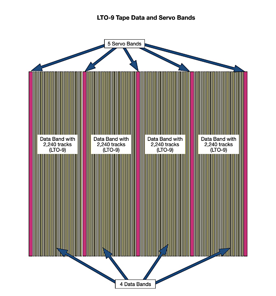
The servo bands are used by the LTO-9 tape drive’s head assembly to position the read-write head over the correct tracks as the tape, speeding underneath the head, can be mispositioned or deformed slightly due to the effect of being pulled through the drive, ribbon quality variations, and so forth. The head assembly is moved sideways across the tape to span two servo bands either side of a data band. It reads these for positioning information that is used, in turn, to position the read-write head over the correct tracks in the data band.
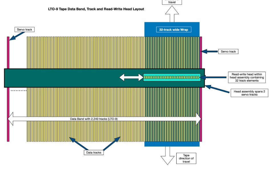
The read-write head has 32 read-write elements. Each element contains a write component sandwiched between two read components – one for reading, the other for read-after-write checking. The overall read-write head reads or writes 32 adjacent tracks at once. This group of 32 adjacent tracks running the length of the tape is called a wrap. The write tracks are partially overlapped, leaving a clearly readable read track, narrower and in the middle of its write track. This track overlapping is called shingling after shingled roof tiles, and is a way of cramming more write tracks into a data band to increase the tape’s capacity.
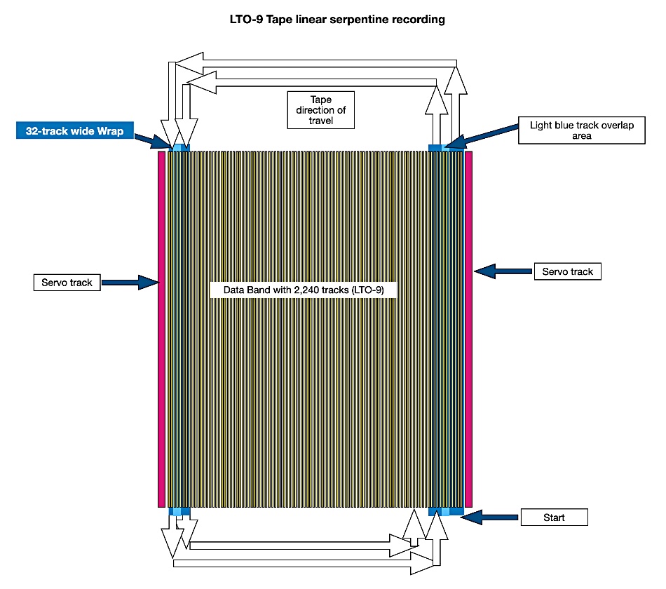
When writing first starts to a fresh tape or to a fresh data band, the initial wrap runs along the rightmost band next to the outer servo band. It proceeds to the end of the tape and then the read-write head is moved to a position over the 32 tracks at the opposite side of the data band. The tape then rewinds, sending the ribbon underneath the heads in the opposite direction.
When the end of the tape is reached and this wrap of tracks is written, the read-write heads are moved again to be placed over a wrap next to the initially written wrap and the third wrap is written. This proceeds with each wrap being inside the previous ones on that data band until the final wrap is written in the middle of the data band. This wrap layout resembles the way a snake can coil itself with its head in the middle of the coil, which is why it is called linear serpentine recording.
An LTO-9 tape ribbon is 1,035 m long , 12.650 mm ± 0.006 mm wide, and 5.2 μm thick. It is made from Polyethylene naphthalate (PEN) and coated with a barium ferrite (BaFe) recording medium material.
There are three ways to increase a tape’s recording capacity: increase its surface area by making it wider or longer, narrow its track width, and shrink the bit area size. Methods of improving I/O include increasing the speed at which the tape passes by the read-write heads and upping the number of read-write head elements.
LTO-10
The LTO-10 format increased capacity relative to LTO-9 but I/O was unchanged at the 400 MBps native data rate. An LTO-10 drive was also unable to read and write LTO-9 tapes, whereas LTO-9 was backward-compatible with the prior LTO-8 generation. Why were these choices made by LTO tape drive developer IBM?
IBM tape storage specialist Josef Weingand told us: “The max read/write speed is limited by physics and the tape material. The tape material is about 6 μm thick. The current max speed is 10 m/sec. With this thin material we are not able to speed faster because otherwise the material will be torn/destroyed.”
This means that “as long as the length of a bit keeps the same length (linear density) we cannot write more bits per second with the max speed of 10 m/sec.”
Weingand pointed out: “Linear density cannot be easily improved – as if the bits get shorter we are not able to recognize the beginning and the end of a bit … Linear density between LTO9 and LTO10 are nearly identical. Capacity scaling is done via track density improvements.” Going from “LTO-9 to LTO-10, track density was massively improved.”
How about increasing tape I/O speed by increasing the number of read-write head elements? Weingand said: “Currently we are writing with 32 tracks in parallel (32 track head). The ASIC /CPU in the LTO-10 drive is already able to work with a 64 track head and a max speed of 1,000 MBps. The next big step will be the 64 track head. However, this a huge development step.” He gave the following explanation:
- Per track we have one read head – one write head – one read head = three heads per track
- 32-track head has 96 head elements, which means 192 cables
- 64-track head will get 192 head elements with 384 cables
Were a 64-element head to be used with the next LTO-11 generation and its 72 TB raw capacity, we could see an up to 1,000 MBps raw data speed. Asked about the loss of backward compatibility with LTO-10, Weingand said: “In general, I do not see many clients move from LTO-9 to LTO-10. Clients with LTO-7 and LTO-8 are now looking for LTO-10. Also, in the past, most clients skip one generation. So, in general, backward compatibility was for most clients not a big requirement.”
He mentioned that “LTO-10 uses a different servo format with 36° angles” from LTO-9 and previous formats to increase the head assembly’s positioning resolution and reduce delay. LTO-9 and earlier generations used a servo format pattern with different angles.
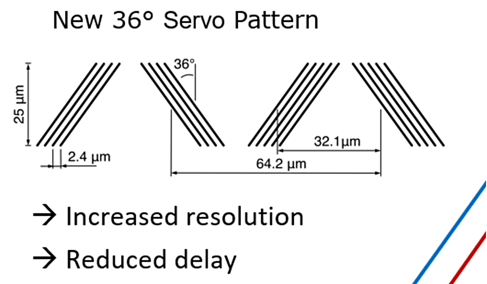
As we understand it, the servo format angle is the angle at which servo tracks are written relative to the tape’s lengthwise direction. The servo tracks are typically written in a chevron pattern (a V-shaped or angled pattern) to allow the LTO tape drive to detect lateral tape motion and maintain head alignment. The angle of these chevrons is critical for ensuring accurate tracking and is standardized across LTO generations to maintain compatibility and performance, and had previously been 6°.
Weingand said: “In the last few generations, we worked to improve the Tape Dimensional Stability (TDS), like with better tension control, and with LTO-9 we did the Media Initialization. With LTO-10, we use a head with tilt-following control.”
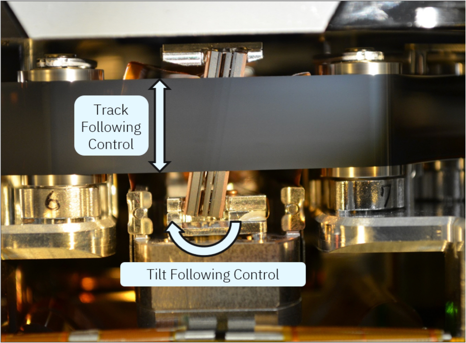
Tilt-following control involves the dynamic adjustment of the angle or tilt of the read/write head to align with the data tracks on the tape. This ensures accurate reading and writing of data despite variations in tape movement or physical alignment.
It appears that head positioning precision had to be improved due to there being more and thinner data tracks on LTO-10 tape than LTO-9.
The changed servo angle and implementation of head tilt-following control, plus the tape customer’s typical migration pattern across generations, are three reasons why backward compatibility was lost with LTO-10.


